
Tiva C Series CAN Bus with MCP2551
In this post I will document how to interface two Tiva C Series microcontrollers over CAN bus with the Microchip MCP2551 CAN transceiver. Messages will be sent over the bus to control the second MCU’s onboard LEDs. The code for this project can be found on Github.
The Hardware
For this project I will be using the Tiva C Series TM4C123G again as well as the Tiva C Series TM4C1294. The 1294 will send commands to the 123G controlling the 123G’s onboard RGB LED. Both of these MCUs have onboard CAN controllers, however these operate at logic levels and do not generate the differential signal needed for CAN bus. To accomplish this we will use the Microchip MCP2551 CAN Transceiver.
All Aboard the CAN Bus
First, a little background on CAN bus. CAN stands for Controller Area Network and is the standard for communications in automotive applications as well as many industrial applications. The two wire bus operates on a differential signal, allowing reliable operation in high EMI environments. Inductive spikes will not degrade the signal as they will effect each wire equally, particularily so in a twisted pair configuration.
Schematic
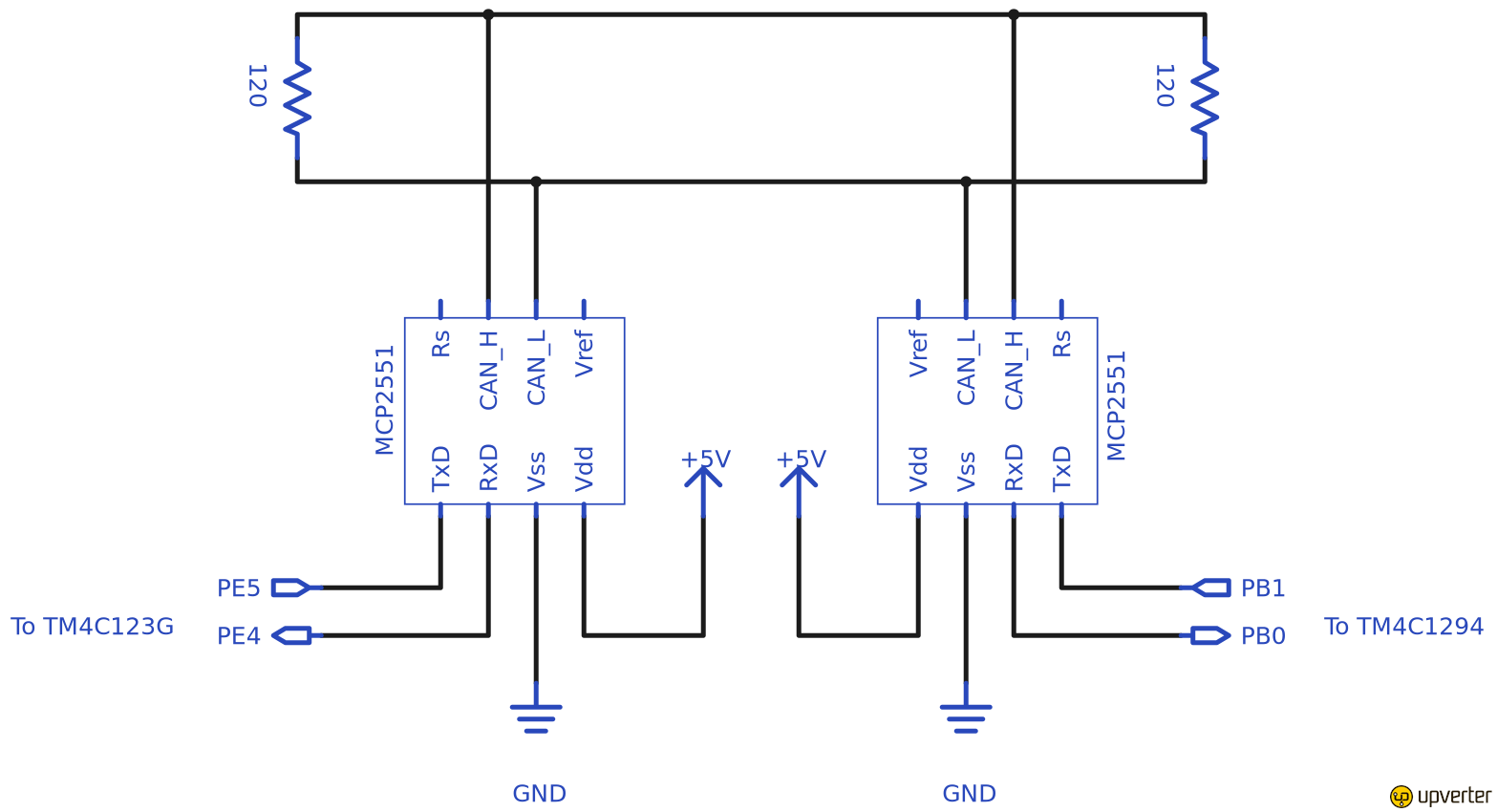
As you can see from the schematic, the bus is terminated by 120 ohm resistors as per the CAN standard. The TM4C1294 provides a 5V pin we can use to power the MCP2551’s. On the 123G we will use CAN0 with pin PE4 as CAN0Rx and PE5 as CAN0Tx. On The 1294 we will use CAN1 with PB0 as CAN1RX and PB1 as CAN1Tx. The datasheet for the MCP2551 is available from Microchip. Take note that the pins in my schematic do not reflect the physical pins on the chip.
The Software
Texas Instruments provides a fairly high level API with Tivaware for interfacing with the CAN hardware on these Tiva chips. I also made use of the RGB driver provided by TI which makes doing PWM control of the onboard LEDs quite simple.
Master
The code is available on my Github. The majority of the code is boilerplate for setting up the CAN and UART peripherals. The master board is going to send a four byte packet to the slave board containing a red, green blue and intensity value to which the slave board will set its LEDs. To accomplish this we allocate an int32 called msgData then create a pointer to it allowing us to access the individual bytes of the int32 in memory. The Tivaware library provides us with a tCANMsgObject struct in which we specify the message ID, mask, flags and the actual message data.
typedef struct {
	uint32_t ui32MsgID;
	uint32_t ui32MsgIDMask;
	uint32_t ui32Flags;
	uint32_t ui32MsgLen;
	uint8_t *pui8MsgData;
} tCANMsgObject;
We will use message ID 1 and set the mask to 0. Since CAN is a bus network, all nodes will recieve all messages on the bus and masks are used to ignore message IDs a node is not interested in. Since we only have two nodes in this network we do not need to worry about masking. We will set the flags to MSG_OBJ_TX_INT_ENABLE which enables triggering an interrupt when the message is transmitted. This interrupt will be used to check if there were any errors in transmitting the message. Once the message object is initialized, we can begin sending colours to the slave board.
unsigned int t = 0; // loop counter
float freq = 0.3; // frequency scaler

while(1) {

	// set up next colour (scale sinf (-1, 1) to 0-255)
	msgDataPtr[0] = (0.5 + 0.5*sinf(t*freq)) * 0xFF;
	msgDataPtr[1] = (0.5 + 0.5*sinf(t*freq + (2*PI/3))) * 0xFF; // 120 degrees out of phase
	msgDataPtr[2] = (0.5 + 0.5*sinf(t*freq + (4*PI/3))) * 0xFF; // 240 degrees out of phase
	msgDataPtr[3] = 128; // 50% intensity

	UARTprintf("Sending colour\tr: %d\tg: %d\tb: %d\n",
		msgDataPtr[0], msgDataPtr[1], msgDataPtr[2]);

	CANMessageSet(CAN1_BASE, 1, &msg, MSG_OBJ_TYPE_TX);

	delay(100);

	if(errFlag) { // check for errors
		UARTprintf("CAN Bus Error\n");
	}

	t++;
}
Rather than simply blinking the LED different colours, we can fade it through the rainbow using three out of phase sine waves. The red blue and green components are each controlled by a sine wave that is 120 degrees out of phase with the other sine waves. This will generate a full spectrum of colours that transition smoothly. The output of the sinf function is scaled to an unsigned byte value (0-255). The intensity is held constant at 50%. Once we have populated msgData we can can call CANMessageSet specifying message object 1 (which is different than the message ID) and a pointer to the tCANMsgObject struct. MSG_OBJ_TYPE_TX specifies the message is being transmitted. We then wait 100ms which allows time for the interrupt to fire, check if the interrupt set the error flag and increment the loop counter.
The interrupt handler is very simple
void CANIntHandler(void) {

	unsigned long status = CANIntStatus(CAN1_BASE, CAN_INT_STS_CAUSE); // read interrupt status

	if(status == CAN_INT_INTID_STATUS) { // controller status interrupt
		status = CANStatusGet(CAN1_BASE, CAN_STS_CONTROL);
		errFlag = 1;
	} else if(status == 1) { // message object 1
		CANIntClear(CAN1_BASE, 1); // clear interrupt
		errFlag = 0; // clear any error flags
	} else { // should never happen
		UARTprintf("Unexpected CAN bus interrupt\n");
	}
}
If the cause of the interrupt is determined to be CAN_INT_INTID_STATUS, this indicates an error condition and the error flag is set to be dealt with in the main loop. Otherwise if the status is 1, this indicates that message object 1 was transmitted successfully so the interrupt and any error flags can be cleared. The second parameter 1 in CANIntClear again refers to message object 1, which was the cause of the interrupt.
Slave
Slave code is also available on Github. We again create a tCANMsgObject and a small buffer for storing the incoming message data. We use ID 0 and mask 0 again which allows the message object to match any incoming message and trigger an interrupt, as specified in the flags with MSG_OBJ_RX_INT_ENABLE. The message object can now be loaded into the CAN peripheral as message object 1 and specifying MSG_OBJ_TYPE_RX so interrupts can be triggered when messages arrive. The interrupt handler is very similar to the master code but sets an additional rxFlag when a message is received. In the main loop we handle the incoming message when the flag is set.
unsigned int colour[3];
float intensity;

while(1) {

	if(rxFlag) { // rx interrupt has occured

		msg.pui8MsgData = msgData; // set pointer to rx buffer
		CANMessageGet(CAN0_BASE, 1, &msg, 0); // read CAN message object 1 from CAN peripheral

		rxFlag = 0; // clear rx flag

		if(msg.ui32Flags & MSG_OBJ_DATA_LOST) { // check msg flags for any lost messages
			UARTprintf("CAN message loss detected\n");
		}

		// read in colour data from rx buffer (scale from 0-255 to 0-0xFFFF for LED driver)
		colour[0] = msgData[0] * 0xFF;
		colour[1] = msgData[1] * 0xFF;
		colour[2] = msgData[2] * 0xFF;
		intensity = msgData[3] / 255.0f; // scale from 0-255 to float 0-1

		// write to UART for debugging
		UARTprintf("Received colour\tr: %d\tg: %d\tb: %d\ti: %d\n",
			msgData[0], msgData[1], msgData[2], msgData[3]);

		// set colour and intensity
		RGBSet(colour, intensity);
	}
}
When the RX flag is set we can set the message object’s pui8MsgData pointer to the msgData buffer and use CANMessageGet to read in the message and populate the buffer. If the MSG_OBJ_DATA_LOST flag was set it indicates that more than one message has been received since the last time we called CANMessageGet and they have been overwritten. This shouldn’t be a problem here as the master is waiting 100ms between sending messages. We can now read the red, green, blue and intensity bytes from the buffer and scale them as required by the LED driver’s RGBSet function.
Plugging it In
We can see from the UART debug output that the colour values are being sent as expected.
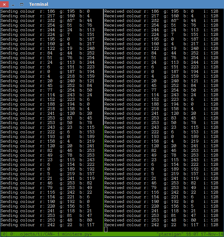
It is cool how the text actually looks like a 3 phase sine wave. I’m using miniterm and tmux here to conveniently show the outputs side by side in a terminal.
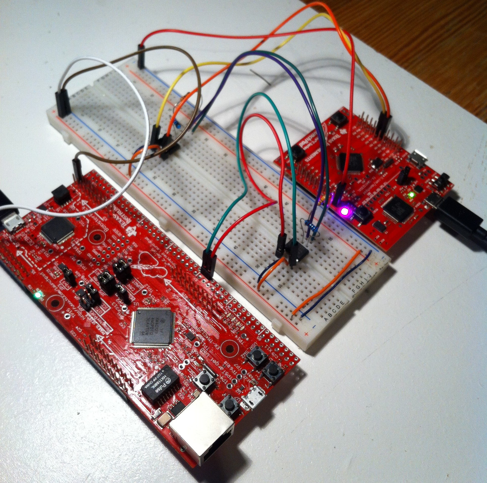
Here is a picture of the setup. You can see the two MCP2551 DIPs on the breadboard.
Short video of the led effect
Converted to WebM with ffmpeg.
Notes
The easiest way to get the code running is to open the “hello” example Code Composer Studio project and replace the code with the code in the git repo.
With regards to CAN bus, the next step is to add another node and begin sending multiple CAN messages with different IDs. The TivaWare driver library docs can be found here, at least until TI moves them again.