
Tiva C Series Bluetooth with PAN1321
In this post I will document how to interface the PAN1321 Bluetooth module with a Tiva C Series Microcontroller and create a simple UART echo program.
The Hardware
The Panasonic PAN1321 is a relatively inexpensive Bluetooth V2 module that can easily be utilized by a microcontroller via a four wire serial UART interface. For one of my current projects using the Texas Instruments Tiva C Series microcontrollers, I needed to add Bluetooth support to interface with a custom Android tablet app. The Roboteurs RB-BT.3.0.1 board breaks out the PAN1321 into a standard TI Launchpad BoosterPack form factor. Any breakout board for the PAN1321 will do but I had the BT.3.0.1 given to me for free so I went ahead and used it. For the microcontroller I am using the Tiva C Series TM4C123G dev kit.
Roboteurs was kind enough to provide a basic example application for the Arduino. The interesting stuff is in PAN1321.h. Seems simple enough, so lets start porting it to TI ARM.
The first thing to do is start digging through the datasheet for the TM4C123GH6PM processor on the dev board. We will discover that the chip supports hardware flow control for UART1, bonus. Let’s make a list of the GPIO pins we will need:
- PB0 - U1RX
- PB1 - U1TX
- PC4 - U1RTS
- PC5 - U1CTS
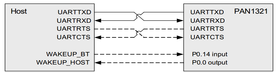
Taking a look at the RB-BT.3.0.1 pinout, we see the same pins are broken out in a four pin header on the board. It is important to note that the BT.3.0.1 pinout is from the perspective of the PAN1321. This means each pin must be plugged into its respective opposite pin on the microcontroller. RX goes to TX and RTS goes to CTS. There is a diagram on page 15 of the PAN1321 datasheet showing this.
The Software
Now that everything is wired up, we can start writing code. I started with the ‘hello’ example project that came with TivaWare. You can follow along with the finished product on Github. There are three important pieces to the code.
Wherefore UART thou Romeo?
First is setting up the UARTs. UART0 is taken care of by the example code and is used to send debug messages back to a serial console on the PC. UART1 is similar however we also need to set up the hardware flow control to interface with the PAN1321. The SysCtlPeripheralEnable call allows us to enable the GPIO ports on the processor as well as the UART peripherals. Next we configure the pins with GPIOPinConfigure and set them as UART pins with GPIOPinTypeUART. The U1RTS and U1CTS pins also need to be set as pin type UART. We set UART1 to 9600 baud (the default for the BT.3.0.1) with a standard 8-N-1 configuration using UARTConfigSetExpClk. Finally we enable hardware flow control for both RX and TX:
UARTFlowControlSet(UART1_BASE, UART_FLOWCONTROL_RX | UART_FLOWCONTROL_TX);Now we are ready to start talking to the Bluetooth module. Like most Bluetooth modules, the PAN1321 speaks the AT command set, which has its roots in early telephone modems. The AT command set consists of text commands which start with the string AT+. The PAN1321 actually contains an Intel eBMU Bluetooth radio, so we can look at the eBMU user’s manual to figure out what commands are supported by the chipset. To make sending commands easier, we need to write a quick utility function for sending strings over UART1. The TI driver library UARTStdio functions only support UART0 so we will have to write our own Println function using the UARTCharPut function.
void UART1Println(const char *buf) {
	while(*buf) {
		UARTCharPut(UART1_BASE, *buf++);
	}
	UARTCharPut(UART1_BASE, '\r');
	UARTCharPut(UART1_BASE, '\n');
}
This function outputs each char in the string and throws a CRLF at the end.
To get the PAN1321 talking to other Bluetooth devices we have to send the following commands
AT+JRESsoftware resetAT+JSECset security modeAT+JSLNset device friendly nameAT+JDISmake device discoverableAT+JRLSregister local service with serial port profileAT+JAACauto accept connection requests
The parameters for each of these commands are documented in the eBMU user’s manual mentioned earlier. Next we wait for +RCCRCNF to show up in the UART indicating we have a connection. We can now enter streaming mode with the AT+JSCR command, wait for the OK response and begin freely sending data through the UART.
Talking to Myself
The final few lines of code simply read in any characters received and echo them back to the Bluetooth UART as well as the debug console UART.
while(1) {
	char c = UARTCharGet(UART1_BASE);
	UARTprintf("%c", c);
	UARTCharPut(UART1_BASE, c);
}
Pretty Pictures
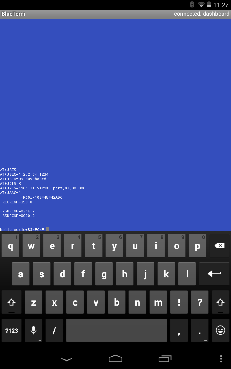
To test everything out, I installed the BlueTerm app onto my Nexus 7 Android tablet. I paired the tablet and connected with BlueTerm. Here’s a screenshot of the Android terminal after disconnecting and reconnecting
And here’s a screenshot of the debug serial console (PuTTY running on PC)
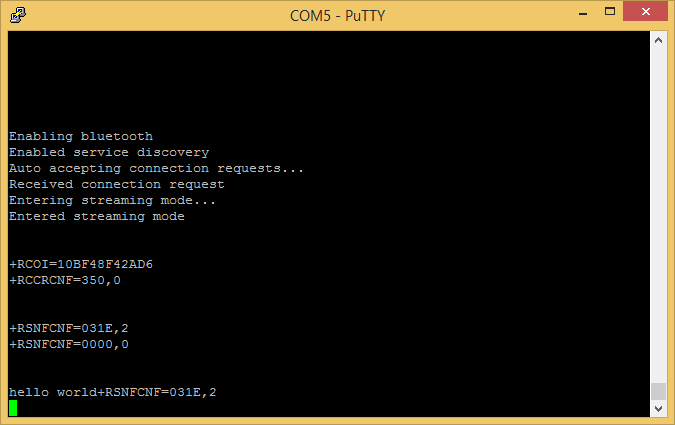
The characters show up in PuTTY as you type them on the tablet, pretty cool.
While debugging, I had the scope hooked up to the RX and TX lines. Pressing a letter on the keyboard repeatedly causes the scope to trigger allowing me to get this capture
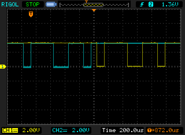
We can see the bits being sent to the uC RX pin in cyan and the bits being echoed back out the uC TX pin in yellow. Since RS-232 is least significant bit first we can start reading backwards: 011001110. Ignoring the stop bit we have 01100111 which is 103 in decimal, corresponding to the ASCII character code for lowercase ‘g’. I was indeed mashing the letter ‘g’ on the keyboard so everything checks out.
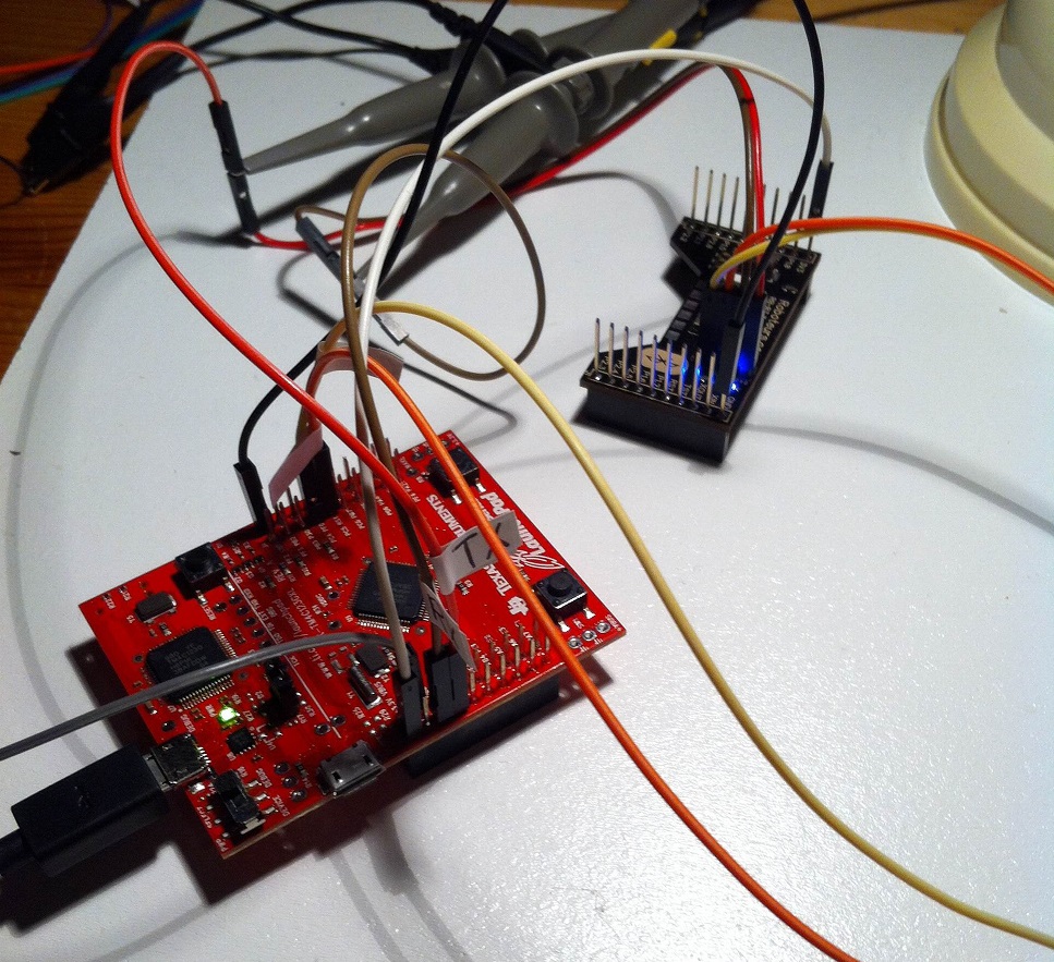
Here’s a picture of my super tidy setup. Though the TM4C123G is compatible with the BoosterPack pin spec, putting it on the dev board would block the PC4 and PC5 pins we need, not to mention being almost useless since we’re only using the 4 pin header in the middle of the board anyway.
There are still a couple things to figure out. Once in streaming mode, AT command responses still seem to be showing up, namely +RSNFCNF which corresponds to a Sniff mode confirmation. The microcontroller is certainly not issuing any sniff commands (AT+JSNF) so I will have to dig into it further to see why this response is being sent from Android. The code that accepts connections needs to be cleaned up. Busy looping on a blocking UARTCharGet is a useful hack but it won’t work when the processor needs to be doing other things until a Bluetooth connection is made, as is the case with my project. The code will have to be moved to a UART interrupt that is executed when a connection is made. I will also admit that I did not take the time to read through the presumably soporific Bluetooth spec and simply assumed that an OK response is a good enough indication of a successful connection.
Notes
Don’t try using the PF0 and PF1 pins on the TM4C123G as U1RTS and U1CTS. They are locked as NMI pins and require unlocking with some funky HWREG calls involving a constant named GPIO_LOCK_KEY. Just use PC4 and PC5 to save yourself the trouble.
Next time on Ohm.Ninja, using the Tiva C Series and the MCP2551 to talk over CAN bus!