
The Beer Daemon
Ever wanted to keep track of how many cans of beer there are in your fridge? Want to be notified if somebody takes one? In this post I will document how to construct your very own Beer Daemon. The Beer Daemon is an internet connected device that sits above the can holder found in many mini refrigerators. It lies in wait using an ultrasonic range finder to measure the height of the stack of cans, ready to notify you should the number of cans start decreasing. The core of the device is the Electric Imp imp001 module which provides a way to get up and running with wifi and cloud connectivity quickly.
The Hardware
Prototype of the Prototype
As a proof of concept, I duct taped a pinger and an Arduino to the fridge and was able to detect the number of cans in the can holder with under an hour of work. Now that the main sensor has been validated, we can design a real prototype.
Schematic
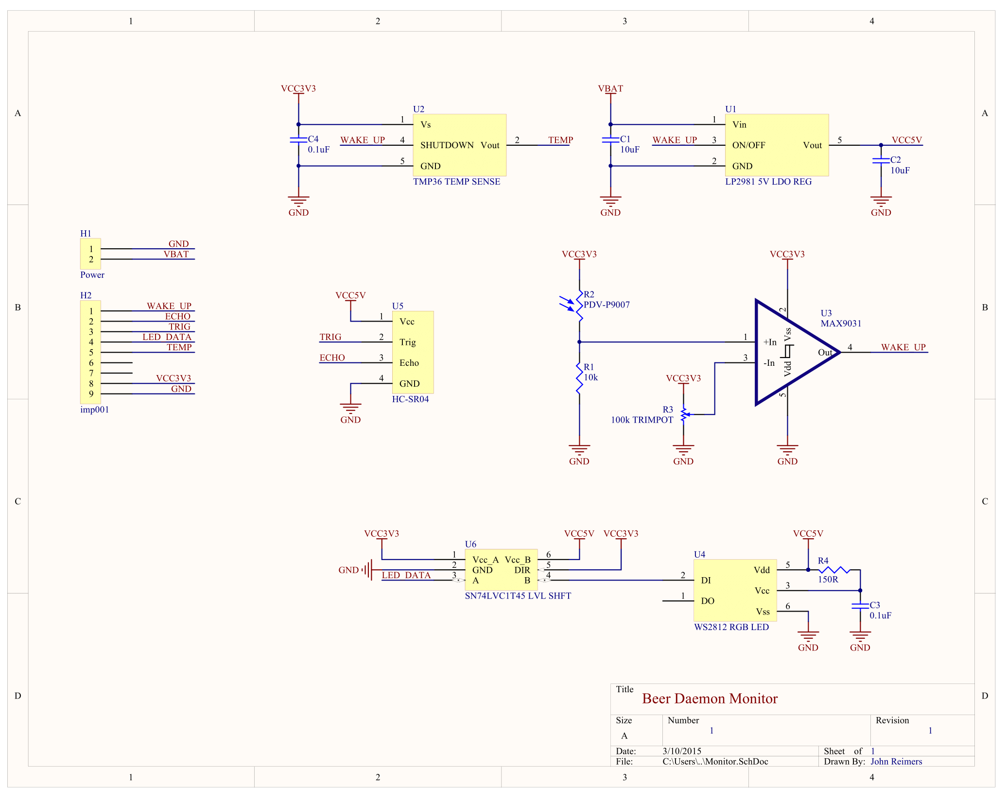
HC-SR04 Pinger
To detect the height of the cans in the can holder, we will use a standard ultrasonic range finder, the HC-SR04. Since the HC-SR04 requires a 5V supply we will need a 5V rail which is provided by the LP2981.
LP2981 LDO Regulator
For simplicity, I elected to power the whole device with a 9V battery. The LP2981 is a standard low dropout linear regulator that will give us a 5V supply for the peripherals that require it.
imp001
The imp001 is an integrated solution for adding network connectivity to a device. For more information see the Electric Imp website. I will be using an imp001 module with an April breakout board devkit. The imp will also handle all the controller logic. The April devkit includes a wide Vin buck regulator with 3.3V output for the imp001 module. The 3.3V buck regulator and 5V LDO will be connected in parallel to the 9V battery.
Bells and Whistles
Beyond the basic ultrasonic sensor, I’ve added a few bells and whistles.
TMP36 Temperature Sensor
The first is a temperature sensor. Having beer in the fridge is not particularly useful if the beer is not cold, so we should keep track of just how cold it is. To accomplish this, I used a TMP36 temperature sensor.
Photoresistor
The second addition is a photoresistor and accompanying comparator circuit. Since this device is totally wireless, it must run on batteries. Power consumption is now an issue and wifi eats a lot of power. The photoresistor will allow us to detect when the fridge door is open so the pinger can begin detecting cans and the imp001 can connect to wifi. Beers disappearing while the fridge door is closed is an edge case that I have chosen not to address, you may have bigger problems if this is happening to you. The trimpot allows tuning the comparator circuit so the output will go high for lower or higher levels of light. The output of the comparator sets the level of the WAKE_UP net. The WAKE_UP net, in addition to controlling the shutdown pins on some of the ICs, allows the imp001 to wake up from deep sleep when the door opens.
WS2812 RGB LED Module
Probably the least important of the bells and whistles, the WS2812 module is an integrated RGB LED and controller with a single wire serial interface. Unfortunately it runs on 5V logic so we will also need a level shifter to interface with the 3.3V imp001.
PCB
Since we have quite a few components and the device needs to be compact enough to fit inside the can holder, I decided to design a small printed circuit board that can sit on top of the April devkit board. The PCB will be soldered to the devkit with 0.1" headers. The pinger will then be soldered to the PCB with more 0.1" headers.
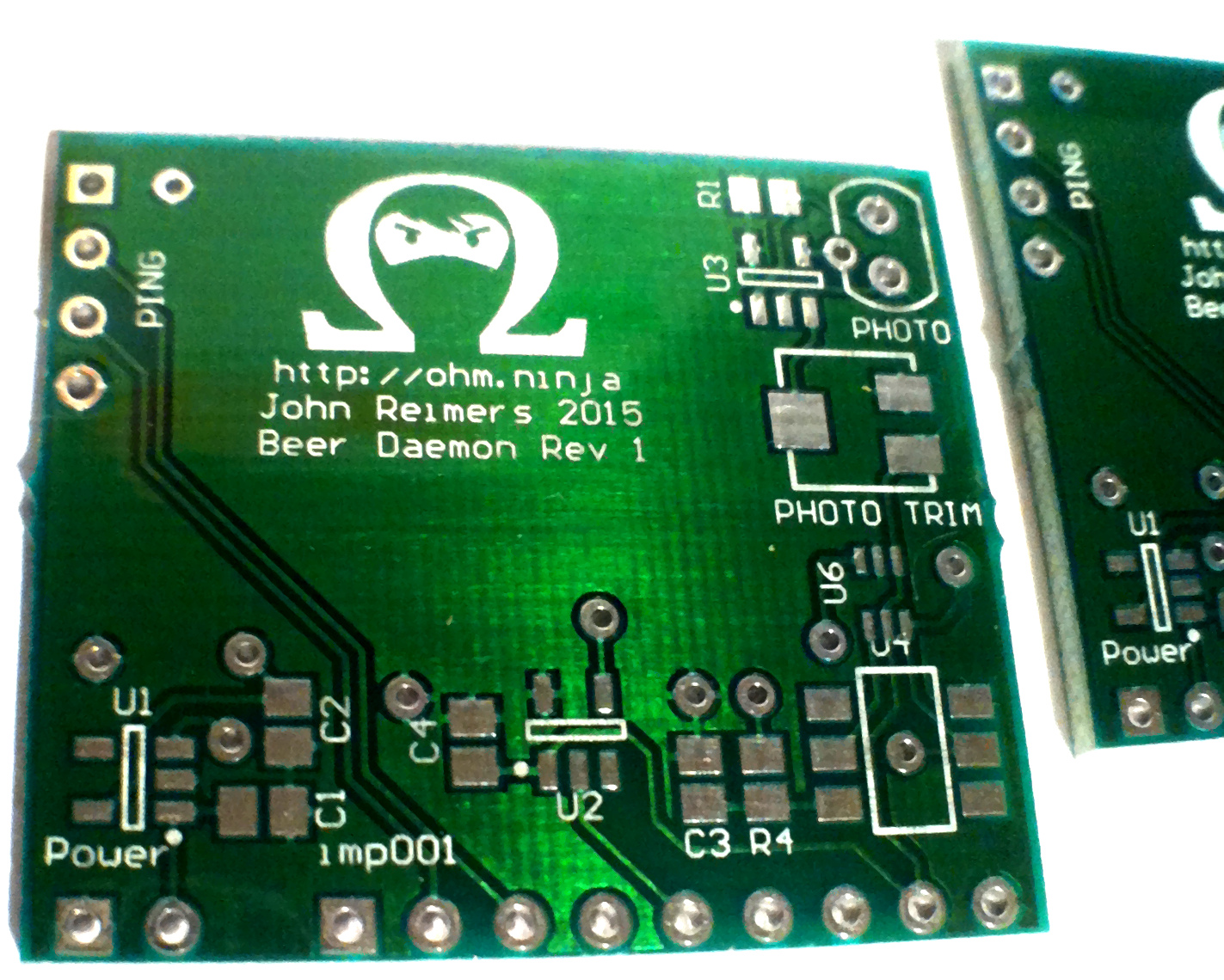
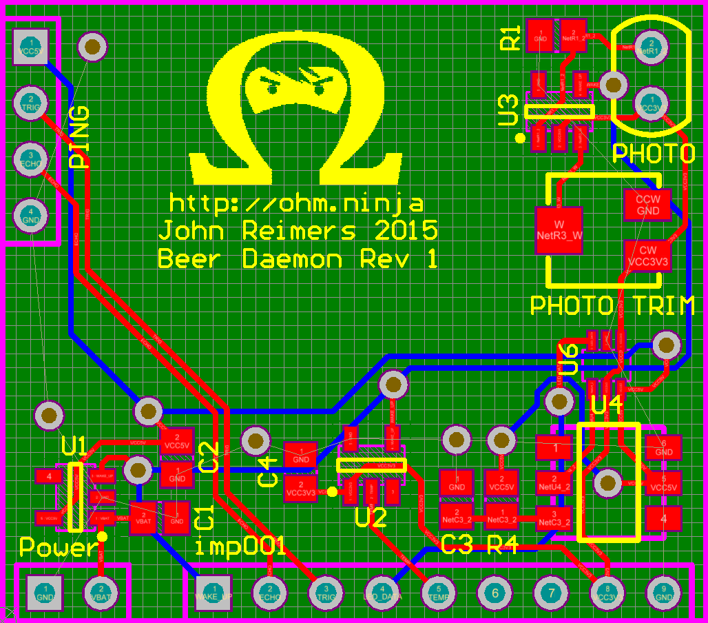 PCB without copper pours
Electric Imp provides Altium files for the April breakout board which allowed me to add identical headers to my board. The April board has two pads for soldering on an external voltage source, in our case a 9V battery. These pads have reverse polarity protection and are then connected to a separate two pin header beside the GPIO header. We will use this two pin header to feed the LDO on the PCB.
The boards were manufactured by AP Circuits in Calgary, Alberta. They did an excellent job and were very reasonably priced for less than a three day turnaround time.
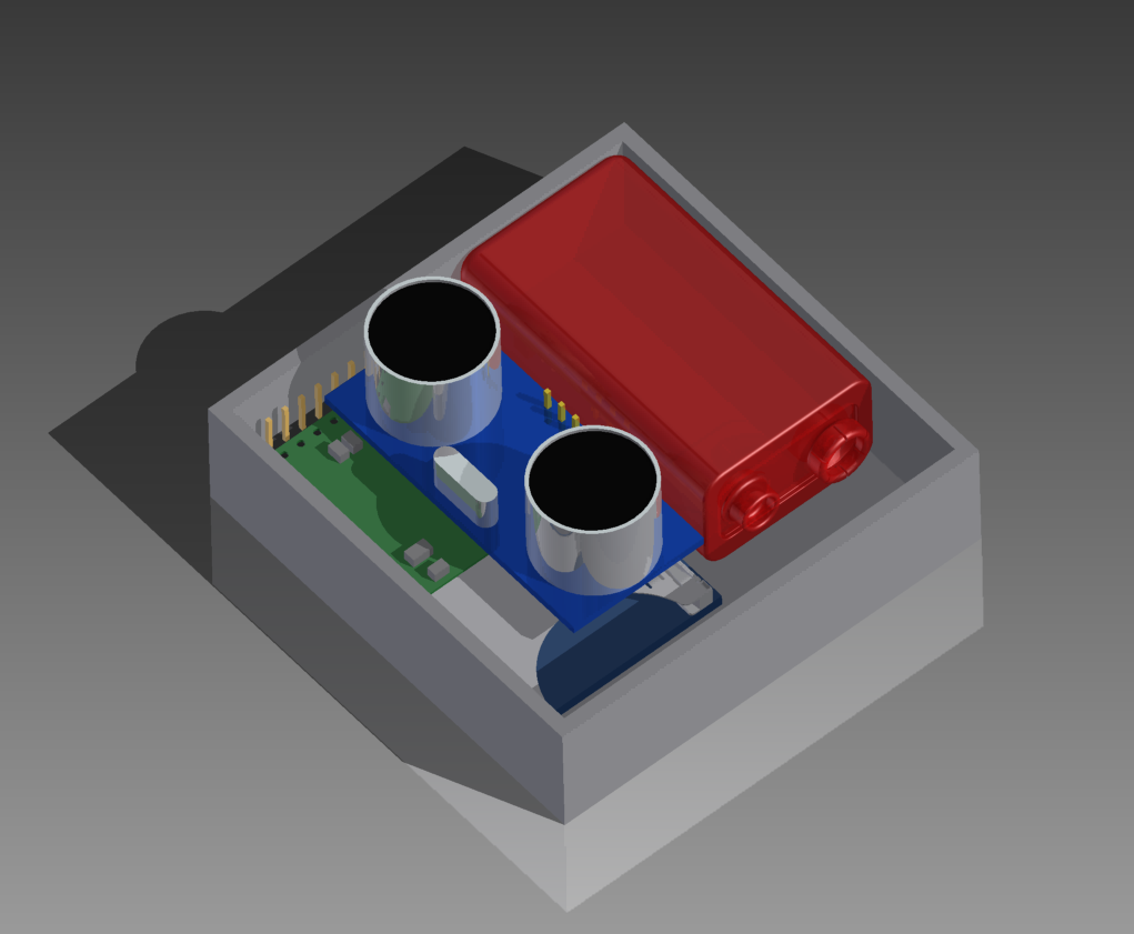
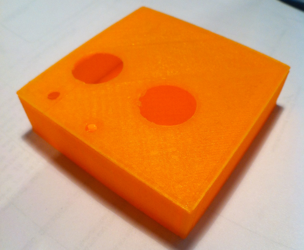
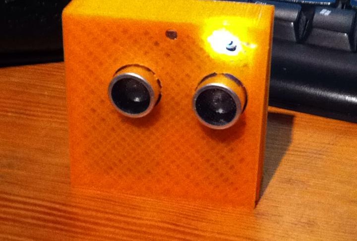
Case
To house everything, I 3D printed a 6cm by 6cm box and friction fit lid with holes for the pinger, LED and photoresistor. I was able to export 3D models of the April devkit board and the PCB from Altium and import them into Autodesk Inventor. I created a model of the pinger and the box and used Inventor to create an assembly of all the parts. The assembly allowed me to cut holes in the lid with the correct placement and ensure everything would fit inside the box.
Printing was done on a Prusa i3 at 100 microns and took less than two hours.
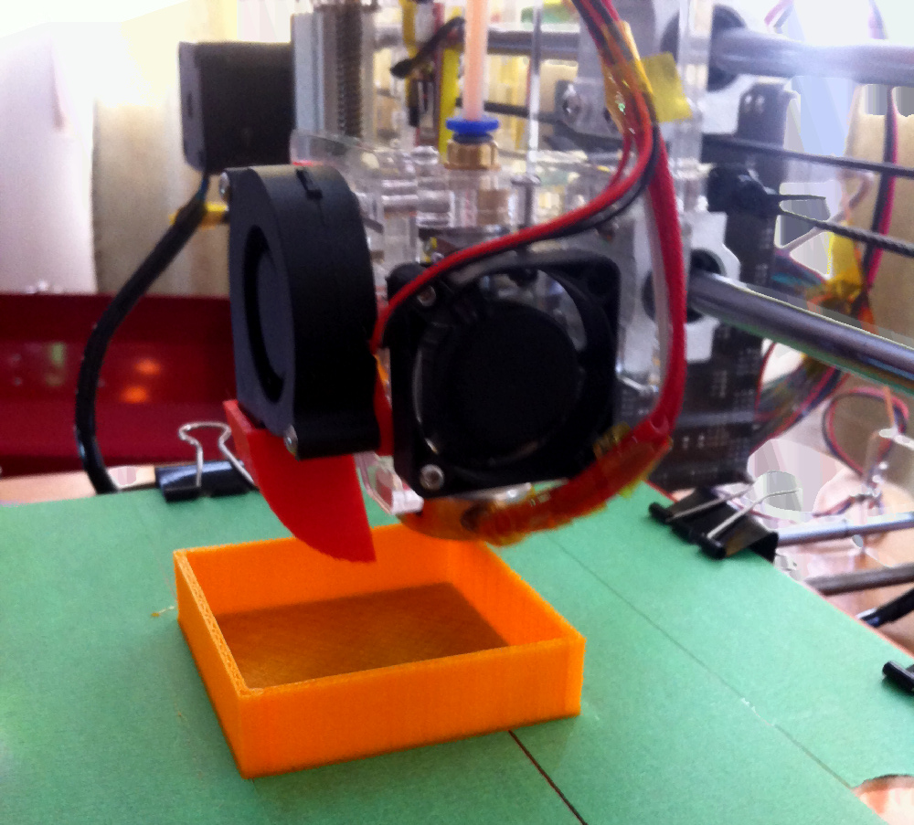
Final print with lid:
Assembly
I swapped some pads on the PCB by mistake and did not check carefully enough, so there are a few more air wires than I would like. I also was unable to get a WS2812 LED module and had to use a WS2812B which was not pin compatible. A revised PCB should make the assembly much smoother.
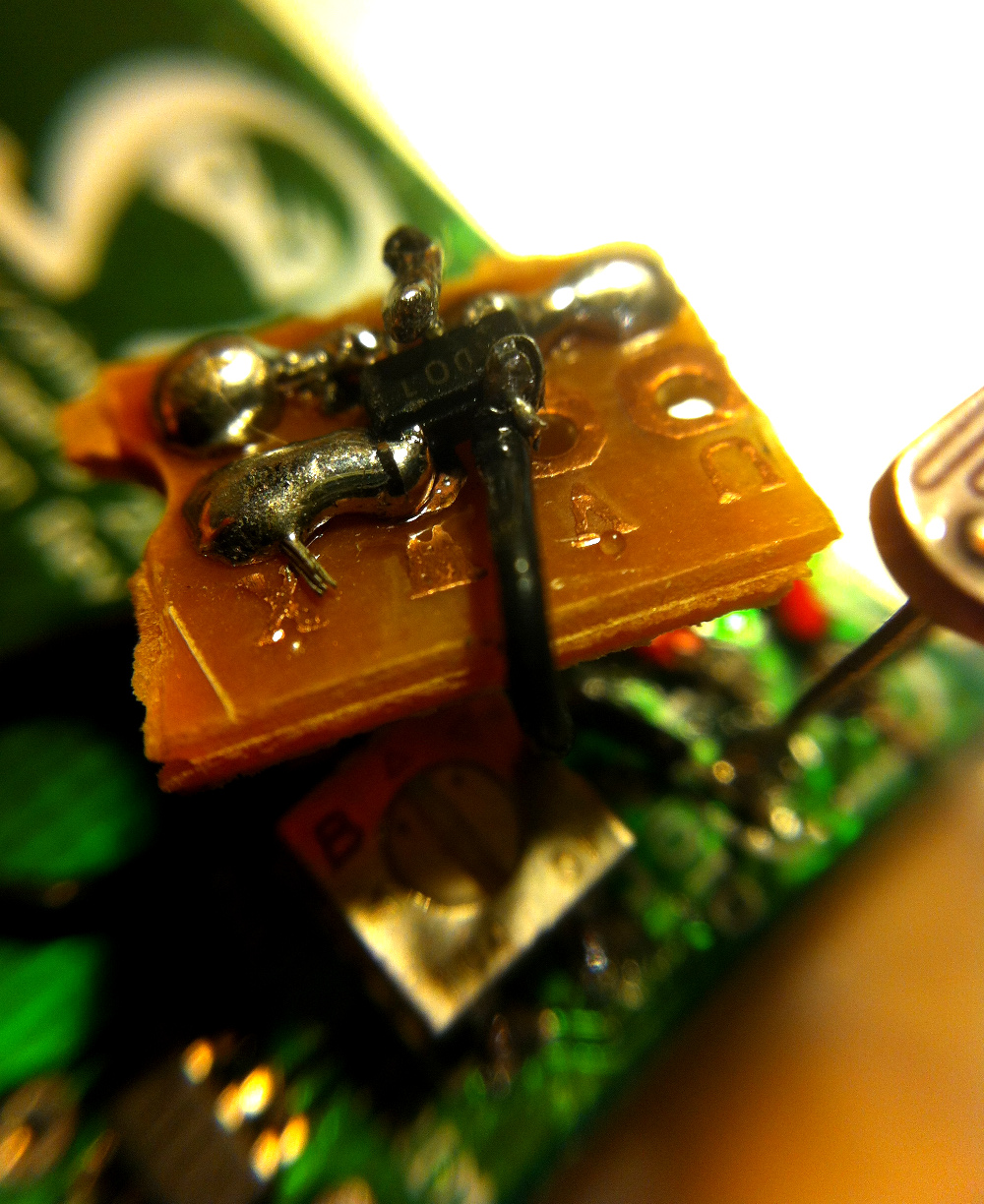
Air wiring a SOT23-5 on some protoboard, nasty! Always double check your footprints kids.
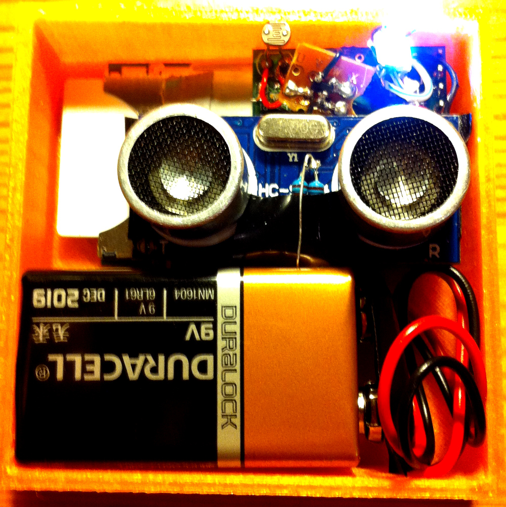
Everything just barely fits in the case. Could use some more tolerances so the lid fits around the battery.
Not a bad looking box. Maybe rounded corners for rev 2?
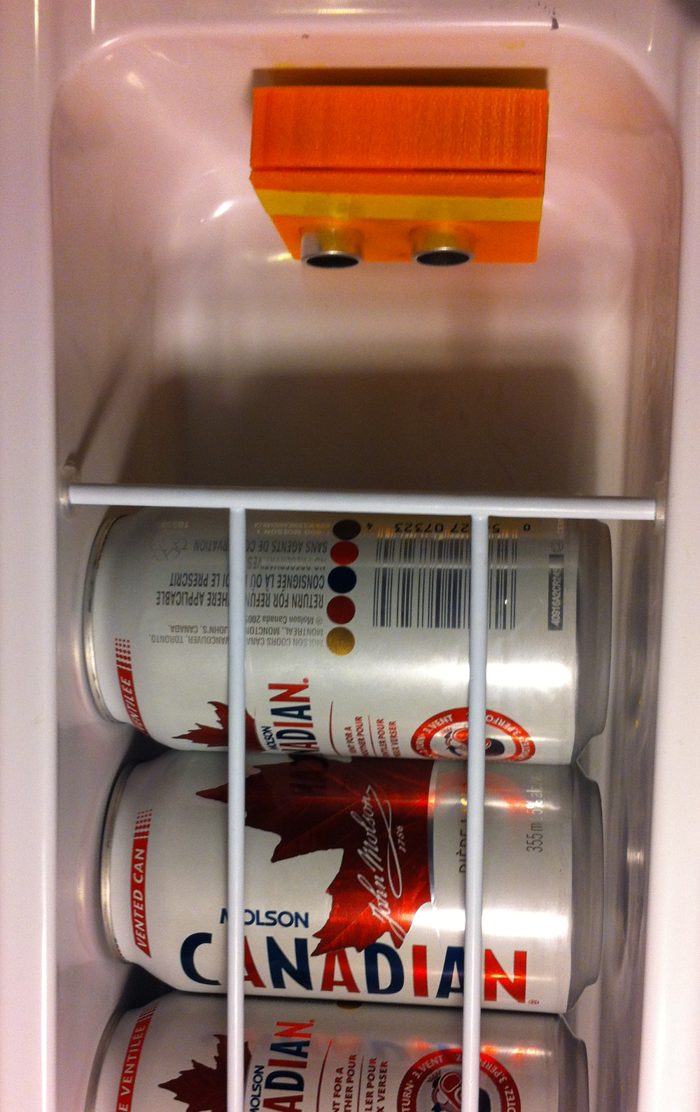
Mounted inside the fridge with double sided tape.
The Software
Electric Imp provides a web based IDE to program your imp module using their Squirrel language. It is pretty slick experience, being able to reprogram the module wirelessly and have a fully featured API with things like HTTP right out of the box. The two important concepts are a “device” and an “agent”. A device is simply an imp module and an agent is some Squirrel code running on the Electric Imp servers that that device can communicate with to access the outside world.
The beer daemon software will operate using a “push” methodology to move data from the device to the agent, then to an externally hosted web app. When the imp is powered up by the photoresistor detecting the fridge door opening, it will begin conducting measurements and sending the data to the agent. The agent will proceed to make a request to one of our web app API endpoints with the new data. The web app will persist and process the data which will be consumed by a web page polling the web service with AJAX.
The web service was written in Python using the Flask framework with a very basic persistence layer based on Python Shelve. The source code for the web service, device and agent are available on my Github.
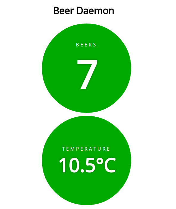
Screenshot of Web Dashboard
Errata
I’m sure anyone who has designed a PCB or two before has experienced this. You check and double check your board and send it off for fabrication. You’re checking the postage tracking to see how soon it will arrive. You start thinking about one part of the board or another and have a sudden realization you screwed up. In my case it was a rookie mistake. After a little experimentation, it seems the HC-SR04 is a 5V device running TTL logic levels. It requires a 5V Vcc to operate reliably, however the logic level TRIG input pin will register a high for anything >2.2V. This is a good thing, the TRIG input pin is connected directly to a 3.3V logic level GPIO pin on the imp001, so we can drive it high without any interfacing hardware. The problem is with the ECHO pin which is also connected directly to a 3.3V logic level GPIO pin on the imp001. Since the Vcc rail on the HC-SR04 is at 5V, the ECHO pin will output a high pulse at 5V. The imp001 pins are only tolerant to 3.6V so we will eventually fry a pin.
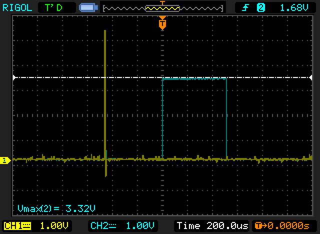
Luckily, there is an easy fix. One of the first things you learn as an EE student in fact: the voltage divider. We can use two resistors to effectively level shift from 5V to 3.3V and keep the imp001 safe. I chose a 10k and a 5.6k because I had them sitting around. The theoretical output voltage for a 5V input will be 3.2V, which is more than close enough to a logic high for the imp001. I managed to fit the resistors on the top side of the HC-SR04 board.
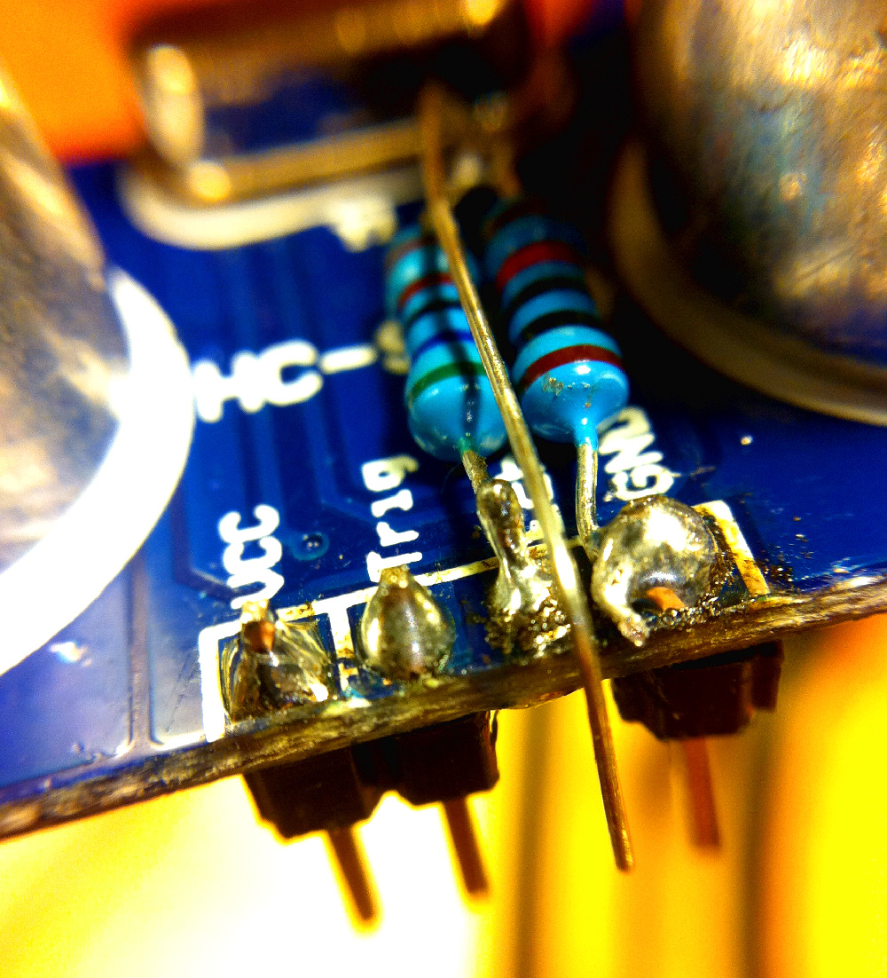
The new patent pending 3.3V tolerant HC-SR04 (but seriously, it’s called a prototype for a reason). The pinger PCB is a bit of a mess from all the soldering and unsoldering I’ve done, however continuity checks out and everything works correctly as we can see from the scope trace.
Other Improvements for Revision 2
- Comparator pads on PCB need to be fixed
- WAKE_UP net should be controlled by software, with the photoresistor connected only to the imp001 wake up pin. This will allow measurements using 5V supply devices even when the door is shut. Currently the door must be open long enough for wifi to connect so distance measurements can be made.
- Software should put the imp into deep sleep when possible
- Software should send notifications to phone
- Move temperature sensor further away from imp001 and 5V LDO to make readings more accurate