
Coreless Axial Flux Motor Prototype
For the final project in a class I took on prototyping methods, we could pick anything we wanted to design and build, within the constraints of the prototyping processes available to us in the lab. Our group decided to build an electric motor as it seemed like an interesting challenge. Based on a thorough literature review mainly consisting of YouTube videos of people building motors out of hot glue or blowing them up, we decided to go with a dual rotor axial flux permanent magnet topology.
Axial flux was chosen to facilitate easier manufacturing on a 3-axis mill and to shorten the flux path which is critical since the motor will be ironless. The stator would be 3D printed with PETG and the rotors milled out of aluminium. Both plastic and aluminium have permeabilities that are essentially the same as air, which is about 4000 times less than the electrical steel laminations found in iron cored machines, and therefore support significantly lower flux densities, requiring a much shorter flux path to achieve any reasonable amount of torque.
Design
We had about six weeks to go from concept to working prototype, so the design had to proceed rapidly.
Magnet Selection
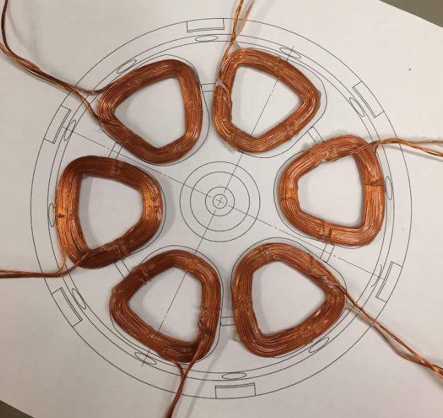
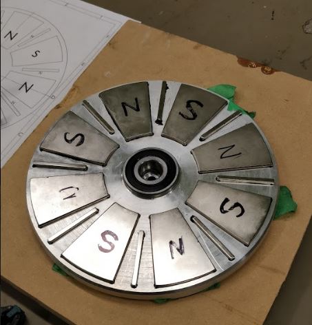
Since we did not have capabilities to manufacture our own magnets, we had to work with what was available and this was a major driver of the remaining design decisions. We also wanted to use a Halbach array configuration to concentrate the flux on the stator facing side of the rotors in order to increase the torque. We were able to source sintered NdFeB magnets in a both a circular wedge shape and a bar shape with the correct polarization to construct the Halbach array. The wedge magnets had an OD of 8" which set the rotor and stator diameters. The magnet arc allows for 8 magnets per rotor for a total of 4 poles. For a three phase machine, the stator will therefore have three pole pairs or six coils.
Winding Design
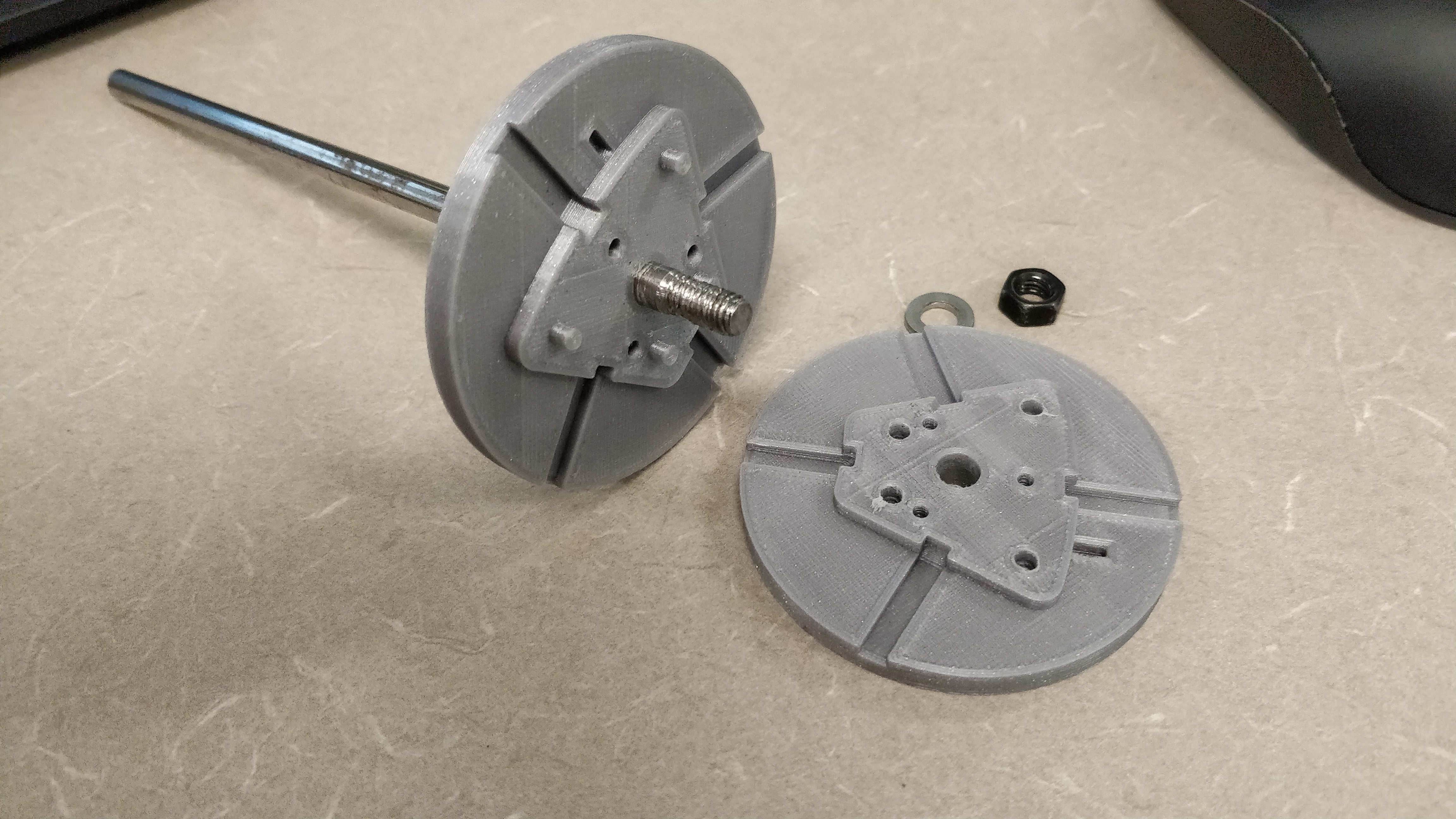
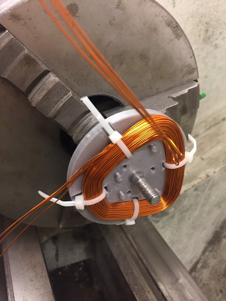
With the magnets selected, a 3D electromagnetic FEA simulation in JMAG was conducted to figure out the coil design. After some parameter sweeps we ended up with 33 turns of 4-in-hand (parallel) 24 AWG magnet wire which would allow up to 30A peak current. Based on a rough guess at the fill factor, the axial thickness of the stator would need to be at least 5mm to fit the coils. A bobbin was designed for the coil winding, with slots for zip ties to hold the coils once wound.
Mechanical
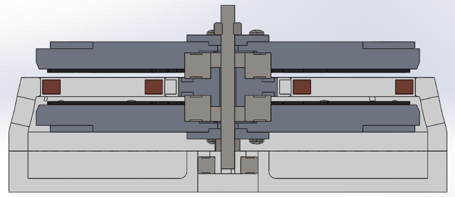
Fixing the rotors to the stator while ensuring good axial alignment turned out to be challenging. The final design relies on a bearing for each rotor. The outer race is pressed into the rotor aluminium and the inner race is pressed into an aluminium hub which is fixed to the stator. A shaft passes through a clearanced hole in the center of the hub and affixes to each rotor, to ensure the rotors are rotationally coupled. The stator was designed to fix to a base plate, forming a shell around the bottom rotor.
Prototyping
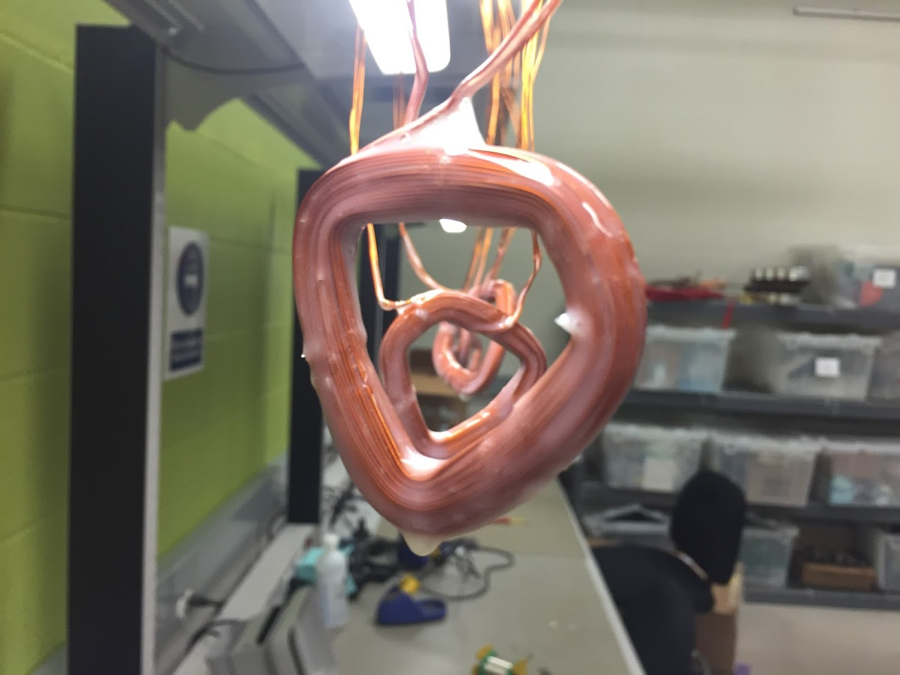
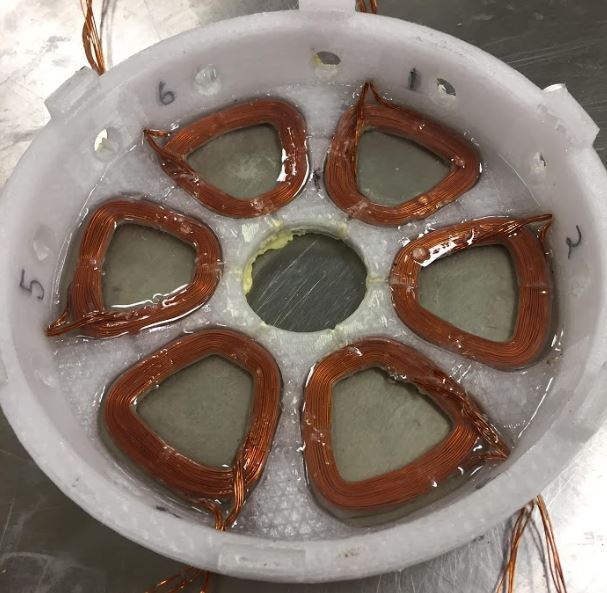
Once the coils were wound, we decided to varnish them so we could eliminate the zip ties. It took several coats but eventually the coils held together fairly well with no zip ties.
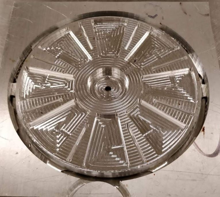
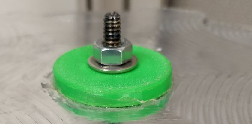
After some test pieces to ensure magnet fitment proved successful, the rotors were milled from half inch 6061 aluminium plate on a Haas mini mill. Additionally, the coil geometry was checked against the stator CAD to ensure the coils would fit.
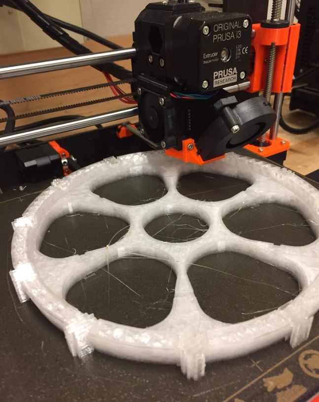
The stator was printed out of PETG on the Prusa i3. It took about 24 hours to print and utilized the entire print bed.
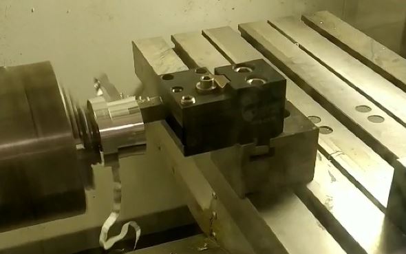
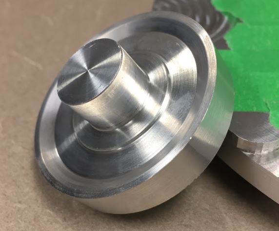
The hub was turned on the Haas mini lathe and took a few attempts before we got it right.
Assembly
With most of the parts complete, we now had to figure out how to assemble everything.
Stator
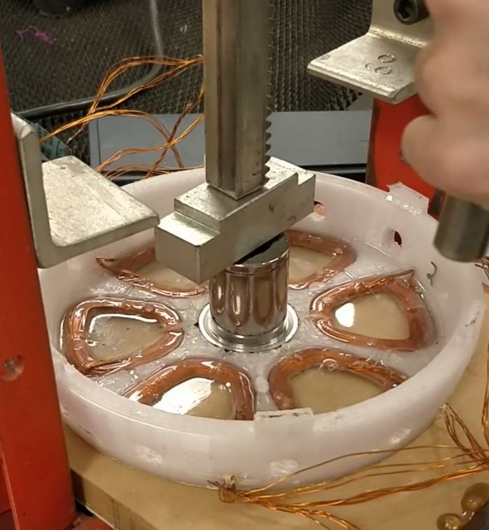
Initially the coils were going to be held to the stator with more zip ties, but this would require increasing the airgap so the zip ties wouldn’t collide with the rotor, potentially causing catastrophic failure. Increased airgap would result in less torque, so we had to come up with another solution. Since we had a large bucket of PT2712 epoxy available from a previous project, we decided to pot the coils into the stator. The epoxy was actually for resin infusion of laminated composites, but based on the material properties we believed it should work well enough for this application.
The stator was clamped to some MDF which had wax applied to allow easy release of the of the part, as well as to prevent the low viscosity epoxy from escaping through any channels in the rough 3D printed surface of the stator face.
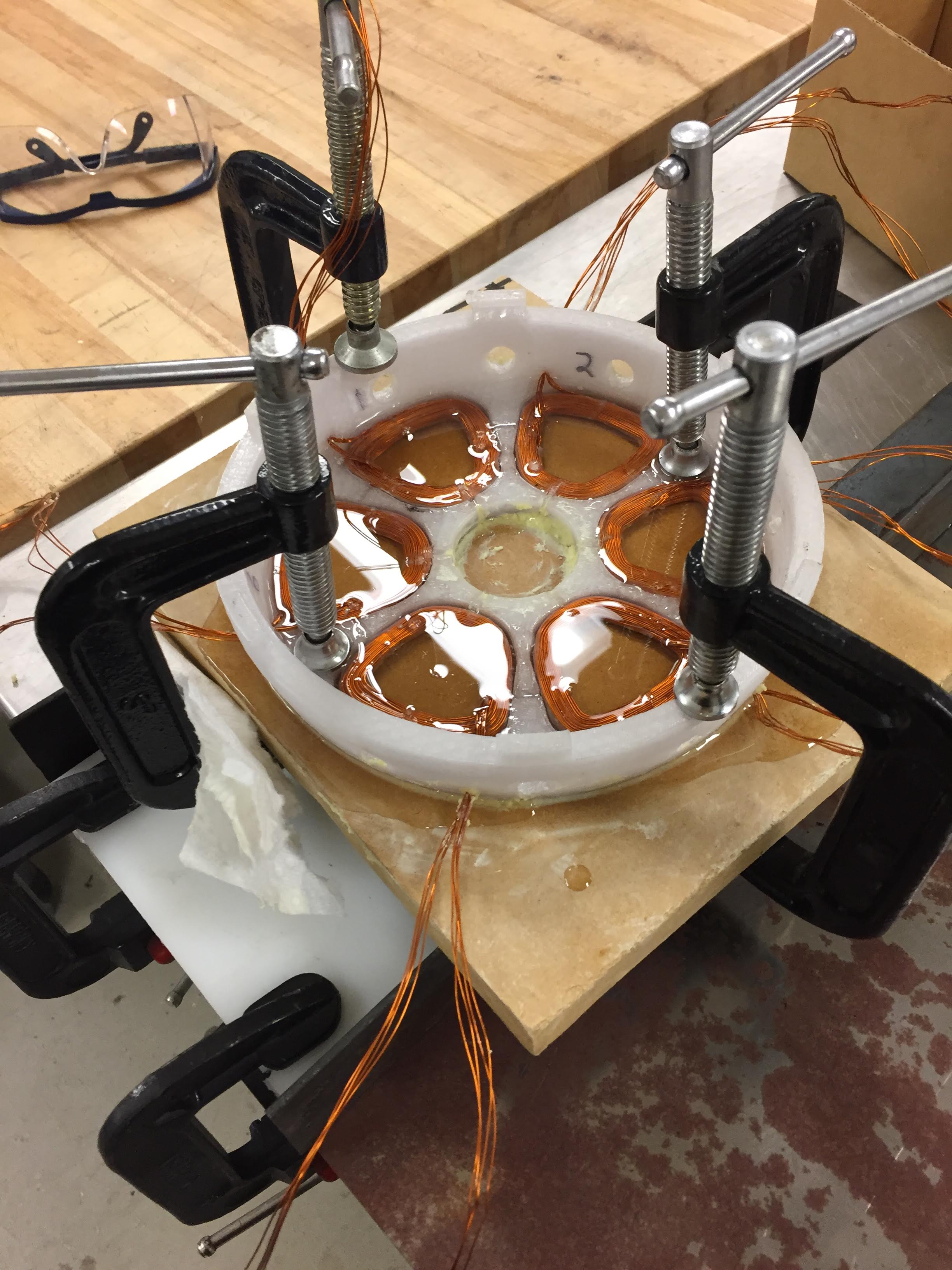
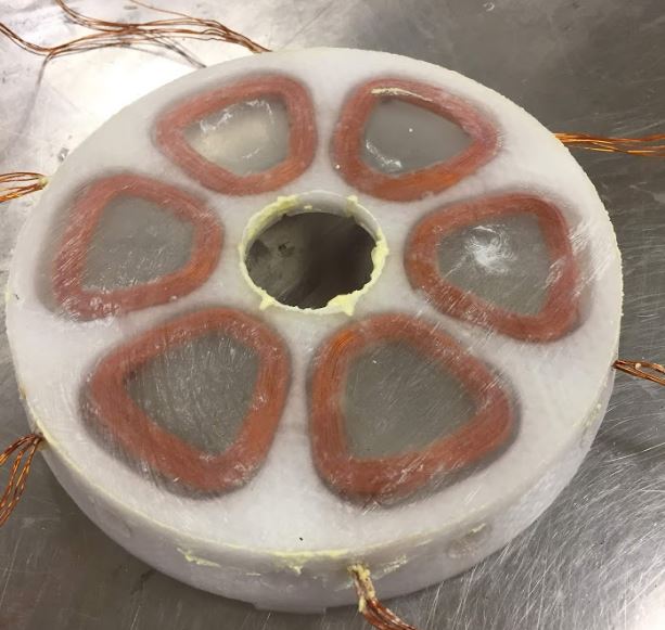
After a 24 hour cure, each coil was completely fixed in a block of epoxy.
The hub was pressed into the stator and retained with Loctite H3000 structural adhesive.
Rotor
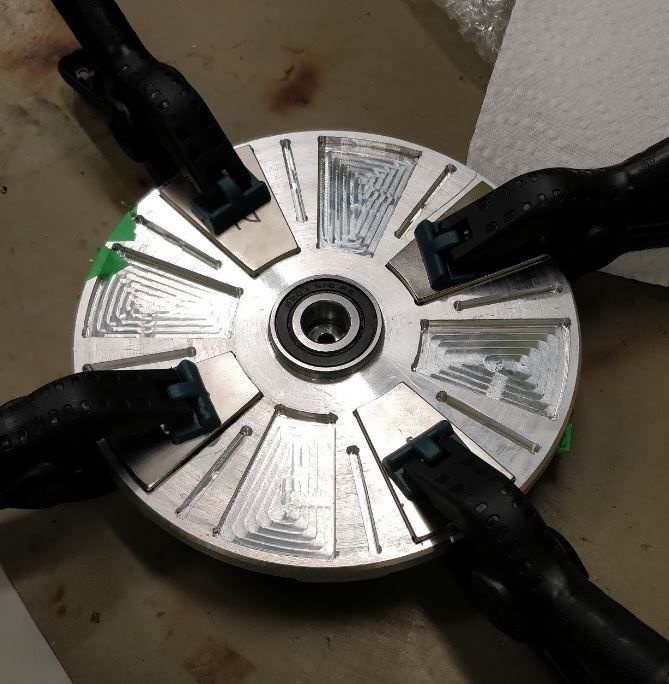
Rotor assembly involved pressing the bearings (although a hammer may have been used before we located the arbor press) and gluing the magnets. Loctite 426 was selected for retaining the magnets since it has good peel strength, a fast fixture time, and we had a tube of it sitting around. The fast fixture time was important as the very strong forces between the magnets can easily pop them out of their rotor pockets and smash them into each other which can be dangerous and expensive. Magnets were inserted and glued in batches and held with clamps. The bar magnets were glued last to create the Halbach array.
Once the two rotors were complete, care had to be taken to keep them from getting to close to each other or any other ferrous materials until it was time for final assembly.
Motor
The two rotors were carefully slid on to the stator hub. The magnets cause the rotors to self align rotationally, so 3D printed shaft collars could be glued on to the rotors with more Loctite H3000 once the shaft was pressed into the collars.
The final assembly:
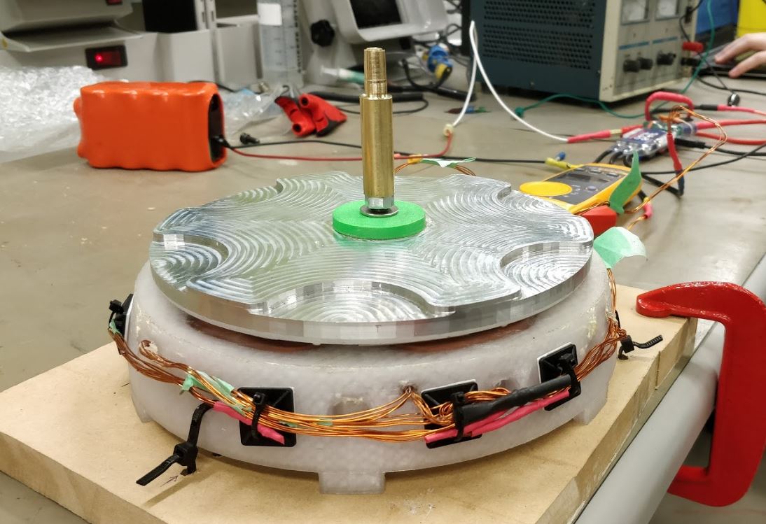
Testing
After checking coil resistances with a milliohm meter, the stator pole pairs were connected in series to form the three phases, which were then connected in a wye configuration. We were able to spin the motor with a drill and see the back-EMF waveforms on a scope, which looked sinusoidal. To get the motor spinning, we used a Turnigy SK8-ESC which is based on the VESC project hardware and runs the VESC firmware. We used VESC Tool to set up the sensorless control from a laptop and monitor the ESC. An e-bike throttle was connected to the ESC and configured as a current command.
Tuning the sensorless control parameters took a few tries, with some fairly violent results. More zip ties were added to hold down the stator.
Once the tuning was sorted out the motor accelerated and spun smoothly.
Since our bench supply couldn’t handle the peak current the ESC required to accelerate the motor from a standstill, we used a 32V Li-ion power cell pack I had built for a previous project, capable of 40A peak discharge. We measured around 1500 rpm as the base speed with the 32V pack. The controller is rated for up to 56 volts, so this speed could be increased considerably still. We don’t have a dynamometer setup that can accurately measure the low torque of this machine currently and we can’t measure the stall torque since the sensorless control cannot provide much torque at 0 rpm. From our estimates, the machine is capable of at least 500W mechanical output, based on FEA results and electrical measurements.
Special thanks to Jack, Adam and Yuli who all contributed significantly to this project.